A transformer is a static piece of electrical equipment which transfers power from one voltage system to another by means of electromagnetic induction. At the basic level, all transformers consist of a metallic coil which carries the electric current, and a ferrous core which creates the magnetic field. The reason for using a transformer is to match the voltage of the load to the line voltage supplied by the utility. The dry type, air-cooled transformers contains no volatile nor inflammable materials, and depends only on the natural flow of air over its coils, and the radiation of heat through its enclosure for cooling. Therefore, it may be located right at the load and requires no special vault.
Transformers are available in a wide array of voltages. The capacity (volt-amps) dictates how much power a particular device can handle before overloading.
The application plays a pivotal role in selecting the correct transformer. Instances where the typical load may spike must be taken into consideration when selecting a particular transformer.
If your application requires a special design not available in stock, we will be happy to accurately and professionally meet your requirements. Marcus will design, manufacture and deliver your custom-made transformer within 7days of your request. For Special Orders: We make dry-type transformers up to and including 600 kVA, auto transformers up to 1000 kVA, and control transformers through 7500 VA. Call with your special requirements.
For Special Orders: We make dry-type transformers up to and including 600 kVA, auto transformers up to 1000 kVA, and control transformers through 7500 VA. Call with your special requirements.
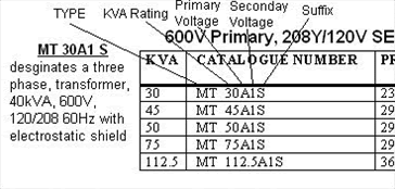
You can form a Marcus model number by following this example or by following our guide below.
Need technical help in choosing the right model? Contact us anytime during business hours.

Determine the KVA, Amperes or wattage required by the load. Transformer size is determined by the KVA of the load. Be sure to add the total number of pieces of equipment involved. The following formulas may be used to calculate the KVA, (VA) or the Amperes required, for either single or three phase installations:
KVA stands for kilovolt ampere or thousand volt ampere. Smaller units 500 VA = 0.5 KVA. Single-phase has two lines of AC power. Three-phase has three lines of AC power, with each line 120 degrees out of phase with the other two.
Important: The KVA of the transformer should be equal to or greater than the KVA of the load to handle current requirements and to account for future expansion.
Single phase
KVA (VA) = Volts x Amps
1000
AMPS = KVA(VA) x 1000
Volts
Three phase
KVA (VA) = 1.73 x Volts x Amps
1000
AMPS = KVA(VA) x 1000
1.73 x Volts
Find out what the supply voltage (or available voltage) is to connect to the primary of the transformer. Line voltage, or primary voltage, is the available power from your utility or local power source.
Determine the voltage required by the load. This is the secondary voltage or output voltage of the transformer. Load voltage, or secondary voltage, is the voltage required to operate the load (lights, motor and other devices).
What is the frequency of the supply source and of the equipment (normally 60 or 50 hertz)? The frequency of the supply source and the load must be the same.
The following charts may be used to select the transformer size required.
Determine the Marcus transformer model number. To do so, you need to consider a few factors first:
Does your equipment require electrical isolation from the supply or will an auto transformer with no isolation do?
- For control transformers: if fusing is desired, a terminal block model is necessary.
- If a control transformer is to be exported, a finger-safe model option may be required.
- The location where the transformer will be installed will determine whether you require no enclosure (open type), an indoor ventilated enclosure, or the various types of enclosures which protect the windings from moisture, particles, dust or contaminates.
Next, select the type of transformer you need. Its kVA rating, primary voltage, secondary voltage and suffix from the chart below.
| TYPE | KVARATING | PRIMARYVOLTAGE | SECONDARYVOLTAGE | SUFFIX |
| MS- Single Phase | A – 600 | 1 – 208/120 | EUR – 50Hz | |
| MT – Three Phase | B – 480 | 2 – 120/240 | S – Elec. Shield | |
| MSWP – Outdoor Single Phase | C – 416 | 3 – 240 | F – 115˚ C Rise | |
| MTWP – Outdoor Three Phase | D – 380 | 4 – 480/277 | N – 130˚ C Rise | |
| RES – Epoxy Single Phase | E – 347 | 5 – 600/347 | B – 80˚ C Rise | |
| RET – Epoxy Three Phase | F – 277 | 6 – 380/220 | P – Sprinkler Shield | |
| MK – K-Factor Rating | G – 240 | 7 – 416/240 | CC – Core & Coil | |
| MDI – Drive Isolation | H – 208 | 8 – 120 | 4 – K-Factor | |
| MAT – Auto Three Phase | I – 240/480 | 9 – 220 | 9 – K-Factor | |
| MATS – Auto Single Phase | J – 2400 | 10 – 220/127 | 13- K-Factor | |
| MTZ – Harmonic Sweeper | K – 4160 | 11 – 240/139 | 20 – K-Factor | |
| MTD – Double Harmonic Sweeper | L – 120 | 12 – 230 | SS – Stainless Steel Enclosure | |
| MHE – Supreme High Efficient | M – 440 | 13 – 230/133 | 30 – 30˚ Phase Shift | |
| RET-MAT – Epoxy Auto 3 Phase | N – 460 | 14 – 120/208/240 | 0 – 0˚ Phase Shift | |
| O – 575 | 15 – 440 | LT – Lighting Tap | ||
| P – 230 | 16 – 440/254 | EQ – Low Sound Level | ||
| Q – 600/480 | 17 – 460 | LI – Low Impedance | ||
| R – 2300 | 18 – 460/266 | CE – European Standard | ||
| S – 220 | 19 – 480 | |||
| T – 120/240 | 20 – 400/231 | |||
| U – 550 | 21 – 208 | |||
| V – 690 | 22 – 380 | |||
| W – 120/208/277 | 23 – 600 | |||
| X – 400 | 24 – 110 | |||
| Z – 1000 | 25 – 347 | |||
| RR – 2200 | 26 – 575/332 | |||
| KK – 4800 | 27 – 240/480 | |||
| 28 – 110/220 | ||||
| 29 – 115/230 | ||||
| 30 – 690 | ||||
| 31 – 690/399 | ||||
| 32 – 277 |
Reliable. Competitive. Custom.
We provide custom products for special “sensitive” applications
such as extra quite, lowest temperature rise, low impedance, smallest footprint, etc.


